B-25 Motors / Retracts / Servos
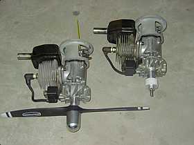
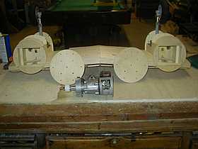
Converted 31cc Ryobi weedeater motors.
I used JAG conversion parts. 16-8 = 7400 RPM
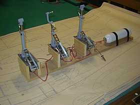
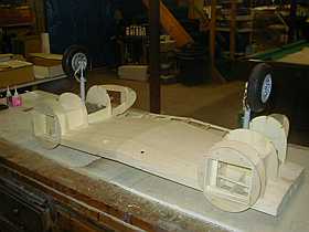
Robart #163 retract set test mounted.
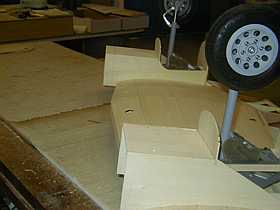
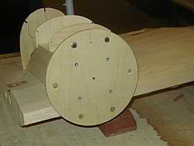
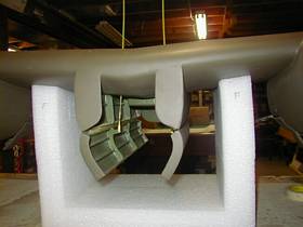
1 inch removed from factory nacelles to allow for the long, slender motors
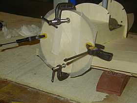
Firewalls epoxied onto the nacelle face.
Removable firewall temporairly mounted.
Retracts test fit and firewalls finished.
Motors mount to 1/4 ply fiewalls which bolt to the 1/4 ply nacelle mounts. Easy access to fuel tanks.
This page was last updated on: March 30, 2014
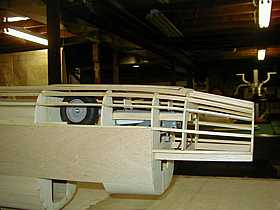
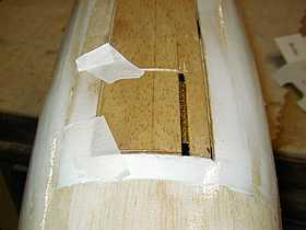
Nose gear and steering pushrod mounted in place before sheeting remaining forward section.
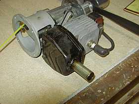
Modified stock muffler and JAG mount.
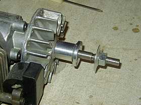
JAG prop adapter and machined down flywheel
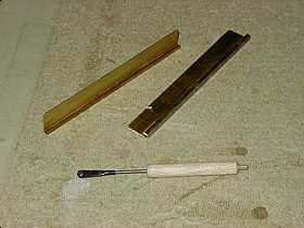
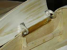
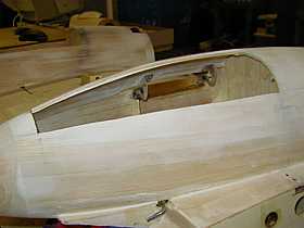
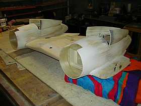
Brass square and flat stock soldered together for a rigid, straight hinge mount. Mockup air cylinder used for spacing and alignment of future air cylinders for gear doors.
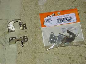
Robart door hinges. I used socket head screws in place of the supplied flat tip screws for ease of future disassembly.
Hinges are glued to the brass plate first to gaurentee perfect hinge line alignment and no binding.
Door is taped in place carefully then the hinges are swung up and glued to the door.
Nearly done hinging the "dreaded" gear doors. Many small tricks to get them to operate properly. While not perfectly scale, they work smooth and are solid.
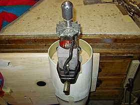
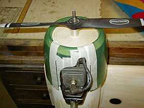
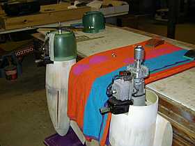
Motors test fit and cowl mounts being measured
Left motor temp. installed to determine throttle linkage, kill switch pushrod, and fuel lines.
Right motor with 1/8th ply disc under prop adapter. Many circles drawn on the disc help center the cowl. Dremel tool is used to cut and grind on cowling to clear engine.
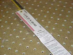
Sullivan 518 giant pushrods used on the rudders, elvator, and steering. Servos are centrally located at the CG point.
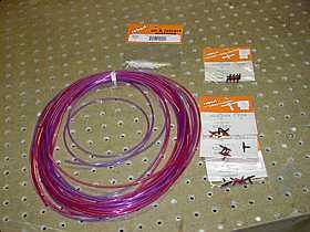
Again, Robart does a great job. I didn't want to couple a bunch of 5ft pieces of airline. They sold me 40 foot of air line by the foot.... that is good service!
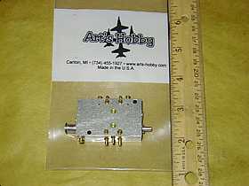
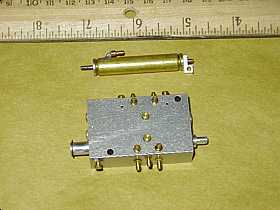
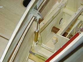
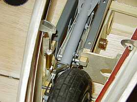
The UP2 valve was ordered from Art's Hobby's, a US dealer for Ultra Precision products.
The 5/16 x 1 inch air cylinders and UP2 control valve are both Ultra Precision products. Very nice machining.
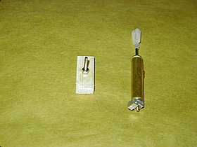
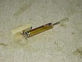
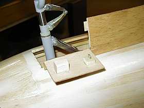
A 2-56 machine screw is countersunk and glued into a 1/4 x 1/2 spruce block for lower cylinder mount.
The lower part of the cylinder will slide over the screw then a 2-56 nut and .049 fuel tubing will hold it in place.
Cylinder is set at maxium length then lower mount and upper control horn are glued in which sets the "open" door maximum throw.
I worked to get the cylinder close to the center of the door so it will have equal torque front and rear...fits tight along side of retract.
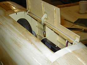
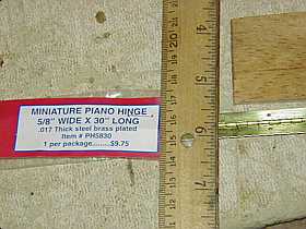
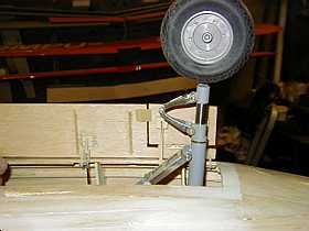
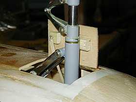
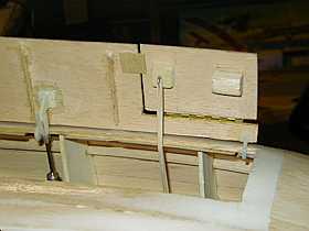
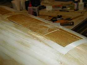
Front air cyinder is centered on the door also. Then the sub door is measured and cut out of main door.
Next a section of small piano hinge is cut off of a strip of hinge. It will be used on the front sub door.
The 1/8th balsa door is cut with a hobby knife and the piano hinge is epoxied into the slit. This allows the door to open easily and not bind.
A rubbing block to keep the door open the correct amount and a nother spruce block with a small hook installed for rubber band tension.
LG door opens fully and LG extends fully.
LG door then closes and sub door remains open due to rubbing block. Tension remains applied due to rubber band tension.
LG door opens again and LG retracts.
LG door closes and a full cycle is complete.
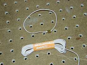
The sub door system appears to work well on the bench. My goal was to not have to use air cylinders on the sub doors. Lack of complexitey, not cost, was my motivation to build my sub door actiavtion in this manner. Final sanding and sealing will need to be done as well as using dress makers elesatic cord instead of rubber bands for tension. The eleastic should last for years. The oppositte end of the eleastic cord will mount as high up in the fuselage as possible so that the tension on the door stays as close to the same as possible throughout the cycling of the main door. I intend to use this system on the main gear doors as well.
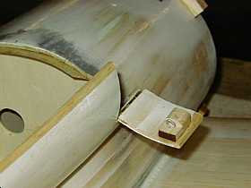
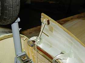
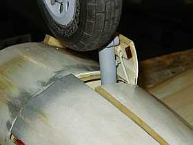
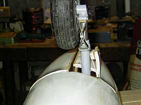
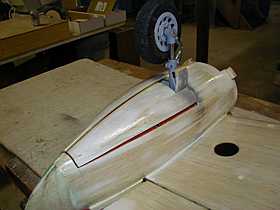
Mian gear sub doors are smaller but hinged exactly the same as the nose gear sub door.
Rubbing block and hook are on same block.
Main gear sub doors work as smoothly and the nose gear door. I'm happy!.
A look from the front.
The complex door construction is now over and I am fortunate that it all appears to work well with my first attempt.
Elastic cord from sewing store. Brass crimp and a drop of thin CA makes any size band needed for the LG sub doors.
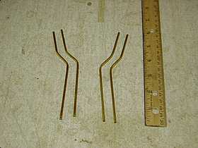
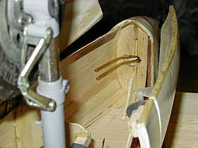
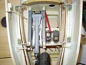
1/8th brass tubing is bent to miss tire when retract is in up postion.
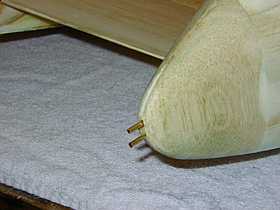
Making use of scale vents to fill and vent my tanks. Upper is fill and lower is tank vent.
Fuel tubes epoxied in. Flexable line will finsh the installation.
Throttle and engine kill servos resting on newly installed servo rails. Red housing will go to throttle. Servos are as far away from motors as possible. ( RF interferrence )
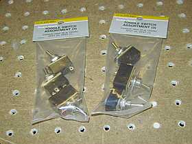
2 switchs will be used to manually ground the magnetos. 2 more switchs will be used for same, but transmitter controlled via pushrod and servo mounted in nacelle. 2 spare switchs??? Who knows. : )
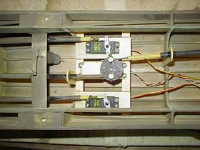
Turret drive motor on left, 1/4 scale center servo for rudders and steering, outter heavy duty servos for elevator halves.
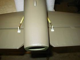
Heavy duty Sullivan pushrods exit under tail and connect to elevators.
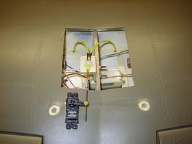
Sullivan flex cables go through main spar and connect to bomb bay doors via home made control horns.
Flex cables come together and are soldered to music wire and activated by a single standard servo on left side. The Turret motor is in fuse but takes up the right side when the wing is mated to the fuse. 1/4 scale flap servo is in bottom center.
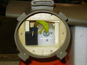
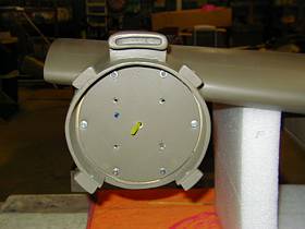
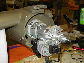
Fuel tank and throttle pushrod.
Firewall bolted in with throttle pushrod and fuel line extending through.
Fuel line attached to carb, engine bolted on, then ball link for throttle attached and manual kill switch installed.
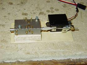
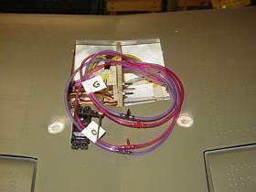
UP2 air control valve and servo mounted to removable plate.
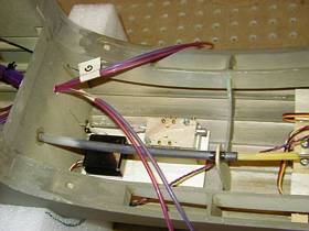
Spare air line will be installed in wing bay so retracts or door cylinders can be maintined easier. "D" door, and "G" gear lines are marked as installed.
All open and down functions use red line. All closed and up use blue line.
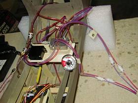
Test for air leaks and function. All is working well. Air valve is not yet mounted in fuse at front of wing saddle.
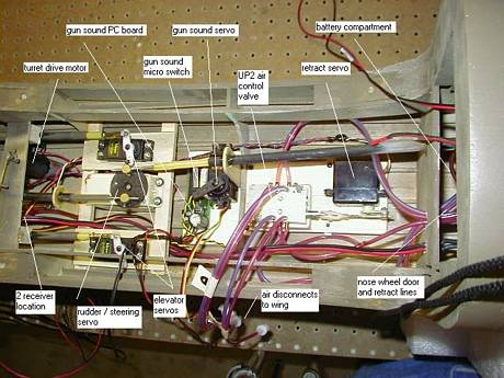
Filling up the fuse with asssorted parts. The air pressure guage is now viewed though the upper navigators dome. An electronic switch from a glider motor will activate the turret motor and gun lamps. 3 toggle switchs will be accessed through the open side gunners windows, they will be the arming switchs for the nav lights, sound system, and turret motor. Air fill valve and 2 radio power switchs are located inside of the crew boarding ladder when it is in the open postion. Twin radio receivers, electronic switch for turret, and 2 PC boards for the gun lamps are yet to be installed back by the turret drive motor.