B-25 Electronics / Detail / Finishing
This page was last updated on: March 7, 2019
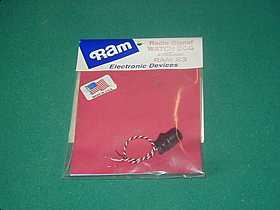
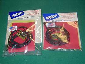
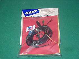
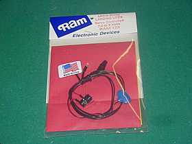
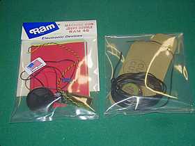
Thanks to Ralph Warner of RAM Electronics. His products allow you to create whatever effects you may have in mind. Visit the RAM Homepage for ideas then call Ralph at 847-740-8726 to talk over your ideas.
Ram 123 Ultra Brite Landing Lites. to be controlled via the retract servo.
Ram 124 Giant scale Nav. Lites. Non-blinking, Non-rotating. Up to 168" wing span.
Ram 01 Adjustable nav lites ( 2 sets ). Using no lens, the clear bulbs will simulate muzzle flash on the 6 50cals. Has adjustable rates for duration and speed.
Ram 46 Machine gun sound module will be used in conjunction with the Ram 01 kits.. Usng two speakers.
Ram 83 Has many functions but I will use it primarily to make sure there is no radio interferrence on my selected chl.
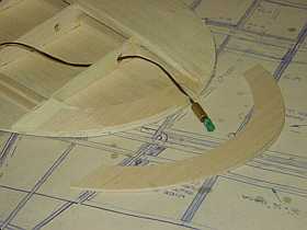
I used an extra 1/8th balsa wing tip to allow for thicker wing tip. 5/16 brass tubing will be glued in, later the Nav lite will slide into tubing.
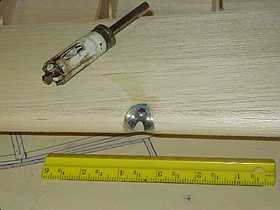
A hole saw was used to drill through wing LE then discardedMini-Mag flashlight reflectors are glued in to hold landing lights.
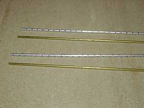
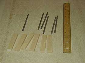
Brass tubing to be cut into lengths for gun barrels, aluminum tubing is drilled and slid over brass to represent the cooling vents.
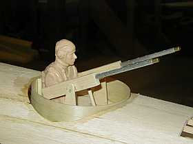
Gun barrels cut, vents slid into place and balsa blocks cut out to make receivers. The balsa is drilled for the barrels and wiring for the muzzle "flash" lamps.
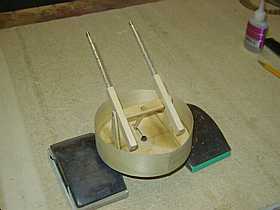
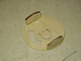
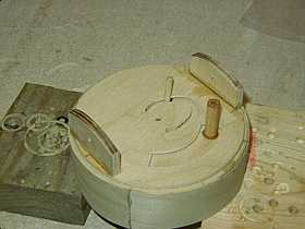
Pivot ams are glued to base and elevation stick glued to gun base. This stick extends through the base to control elevation of guns as turrets moves.
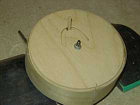
Mounting plate has curved cutout milled into it with dreme tool. Rotating the base and mounting plates actuates the gun elevation.
Mounting plate with lugs glued on, these have 4-40 bling nuts inplace for easy mounting. Notice cutout for actuation arm.
3/8th wood dowel epoxied into hole in base of turret. Dowel is tapped for 4-40 ball connector. Small, continous rotation geared motor drives the turret in a swinging motion much like wiper linkage on an automobile.
Mounting plates glued to fuselage. Turret assembly is easily mounted through fuselage wing opening. ( actuation arm not yet installed at time of photo ).
Turrets swings approx. 45 degrees to each side from center and gun elevation changes approx 1 inch as it swings. Turret canopy will slide down onto base and be attached with small screws.
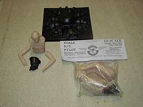
Pilot figures, 3 1/2 of them : ) , were purchased through Nick Ziroli plans. The vacum formed dummy engine faces are also from Nick.
I strung a couple of muzzle lamps, hooked up the sound board and speakers, and C clamped the motor/gearbox to a fuselage former for a test..... It works GREAT!
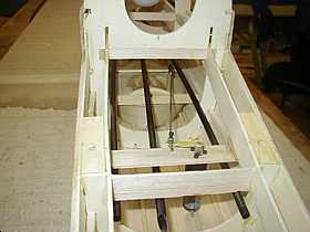
The motor / gearbox and drive pushrod for the turret is now permantly mounted. It is mounted up over the wing to help reduce tail weight.
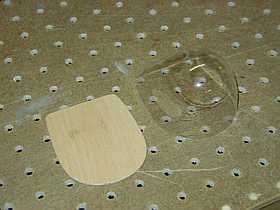
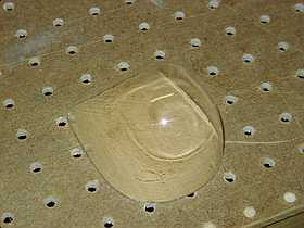
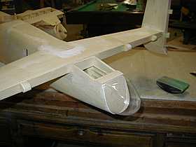
Rear glass trimmed and then layed on 1/16th balsa then balsa traced and cut.
1/16th balsa sanded lightly to fit glass exactly
1/16th balsa glued to tail of airframe and then airframe sheeting sanded until it is slightly larger than the 1/16th. This makes a smooth, flush fit when the glass gets glued in place later.
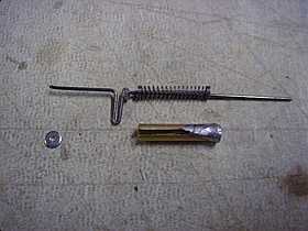
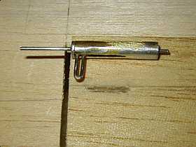
Ink pen spring, 1/16th wire, brass tubing, and a couuple of those left over dubro e-z connector washers
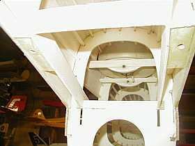
Only the tang will stick up through the slot of the crew ladder. A slight pull forward will release the latch and open the ladder for access to the switches and accessories
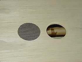
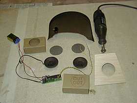
A&W Hobbies router used to install speakers for gun sound. Car speaker grill cut down to 2 inch round for grills. The router is great for all inlays.
The actual lower wing panel cut out and routed. The grill will be epoxied in the flanged area and be flush with wing skin. Speaker is glued in from inside of wing before final sheeting.
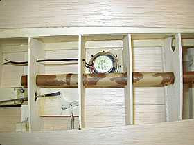
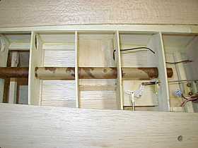
Speaker glued in and wires run to center
I made my own speaker box from balsa sheeting.
The speaker needs to be sealed from the backside for best sound.
Canopy parts being cut and test fit before glassing the fuselage.
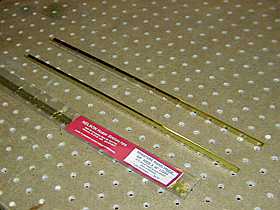
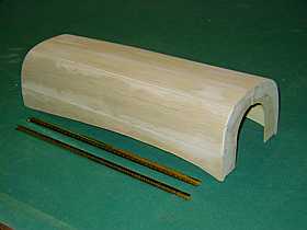
Strips of piano hinge will be installed approx. 1/2 way up each side and will allow bomb bay to open smoothly.
Piano hinge strips from Nelson Hobby. I bought 2 sizes and will use the smaller on hatchs, the larger for the bomb bay.
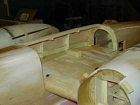
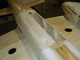
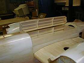
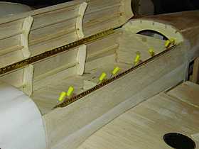
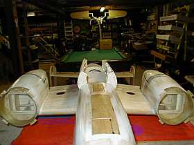
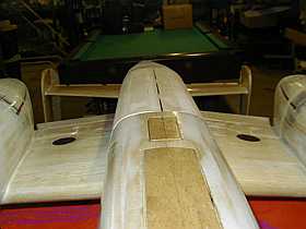
Bomb Bay shell is sawed in half and one side is fit and glued to wing only, not fuselage
First side is now hinged and second side glued in place. Door is cut free of second side awaiting hinging.
Picture of hinge on first side.
Second side piano hinge being epoxied onto the sidewall. Once dry, wax paper is slid in place, hinge folded in over it and door epoxied to the top of the hinge.
Bomb bay doors open and close very smoothly..
Next will be to install door stops and figure out how to acutate them.... minor problem. : )
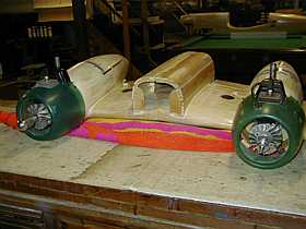
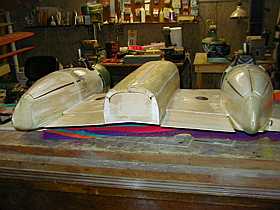
Rear of bombay is sheeted with balsa.
Front of bombay is open for easy acess to battery compartment in fuselage.
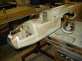
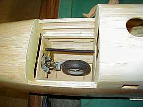
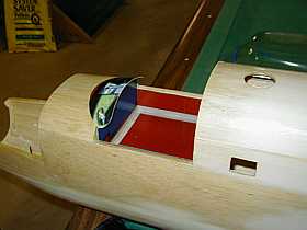
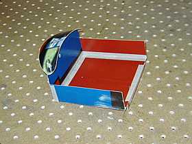
All clear parts taped in place and approx 90 holes drilled at 1 inch apart for the 2-56 button head screws that will hold the canopies in place
Cockpit floor will rest on top of the fuselage crutch. Too crowded for rudder pedals unless you are building a scale model to be judged for points.
Cardboard is being cut and placed for floors, sides, and dash panel area.
Cockpit areas will be held in with a few small screws on each side and removable for repairs or upgrades.
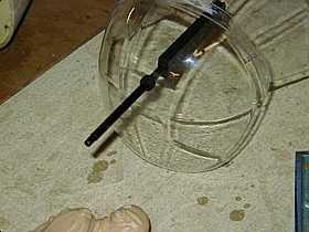
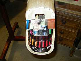
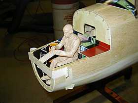
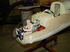
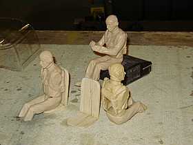
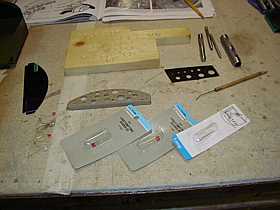
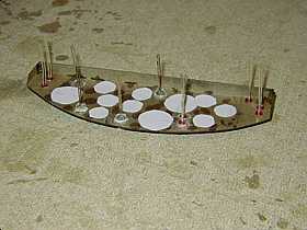
A 25 cent grommet from the hardware store makes good bushing for the machine gun to exit through.
Cardboard being cut and fit for front flooring and sides.
Test fit of front gun and position of airman.
Dummy 50 cal. receiver taped to nose section. Arms and hands glued in proper postion to hold gun.
Seats from 1/4 balsa. Pilots trimmed to fit floorboard and part of chute pack cut off so they set back properly.
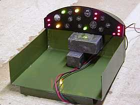
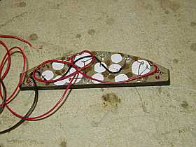
Dash panel made of cardboard. Using hole punchs, clear pastic and paper gauges.
12 assorted color LED's from Radio Shack to add a bit of life to the panel. All LED's glued in with the cathode lead towards bottom of panel for ease of wiring later.
Solder 4 LED's in series, then solder the 3 sets of 4 LED's in parallel. It will runs hours on a 9V transistor battery.
My dash panel will be wired in parallel with my 9V Navigation lights. One battery, one switch.
August 2001 issue of R/C Report magazine contains my dash building article. ( Less LED feature )
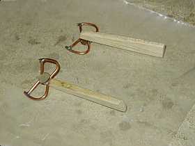
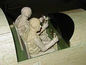
14 gauge solid copper house wire is bent around 1/8th ply form to shape control yokes. Upper yoke cross bars soldered in and cardboard dash gauge punchouts for center caps.
Pilots seated and many arms, heads, hands cut off and reglued to shape them each differently. Fine toothed band saw works great with these figures bought through Ziroli.
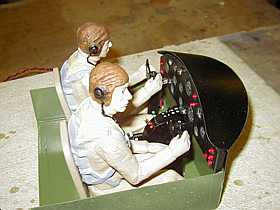
Center console, some paint, and part glued in place make the cockpit look much better.
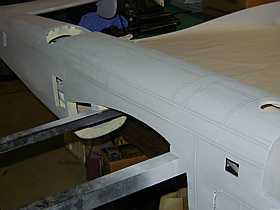
3M brand 1/16th wide masking tape used for panel lines.
When airframe is in a condition that would be ready for paint, the 1/16th tape is applied. One more coat of primer / filler and sanded until tape shows through.
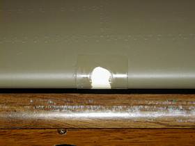
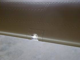
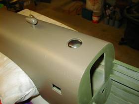
The same area with paint and the domed up top window.
The rivets don't show well due to flash..
.010 clear plastic is glued over the landing light, then masking tape is cut...put in place, and painted..
Rivets and flat clear painted on...then untaped to get a realistic landing light that is very bright.
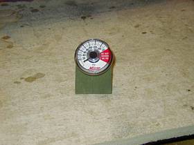
Automotive air bubble guage with 1/16th tubing soldered on to fit air line. Gauge can be viewed through side gunners window.
Great friend and fine modeler Don Incoll sent me a discarded PC board with micro LED's to see if I might be able to use them on the B-25 dash. I mistakenly applied too much voltage to the board and overheated the works. None the less..the seed was planted to build an instrument panel with illumination. I'm proud to give full credit to my pal Don for this feature even if I destroyed his parts and resorted to Radio Shack parts to continue on.
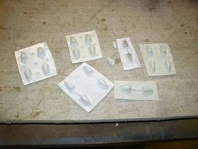
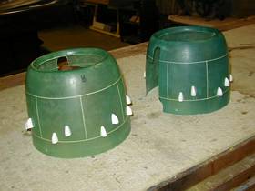
28 Clayton stack fairings vacum molded for the engine cowls.
Cowls wet sanded, clayton stack fairngs glued on and 1/16th panel line tape in place and ready for primer.
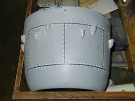
Primered, dry, sanded, and tape pulled off. Rivets now applied and drying. Color coat will be next. See the "tools" page concerning the rivet tool used.
A big thanks to Chad Veich, fellow modeler, and r/c forum moderator for vacum forming all the Clayton stack fairings for this model. Chad offered to help me with the vacum forming and did a beautiful job on the parts. This is all from a person I have never had the pleasure of meeting. What a guy!
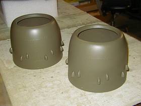
The cowls with paint..........
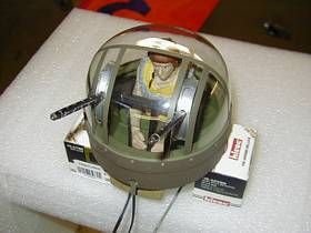
Upper turret all painted and assembled, Including the muzzle flash lamps.
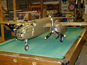
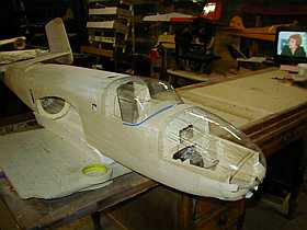
Assembled and looking like an airplane for the first time. Nearing 37 pounds and balanced without additonal weight. Building light in the tail pays off.